If you are having trouble with a Kingfisher instrument, please check the following:
2-way Loss Test Set fails to start 2-way Autotest:
- Check that the connected instruments are of the same model/part number.
- Check that fiber is connected to the 2-way ports of the instruments. Do not connect the fiber to power meter port for this operation.
- Light (especially fluorescent) entering the instruments via power meter ports may result in Autotest malfunctioning. Cover power meter ports on all the connected instruments with opaque dust caps.
An instrument won't respond, or is generally malfunctioning:
- If the instrument runs on alkaline batteries, put in fresh batteries.
- If the instrument runs on re-chargeable batteries, try using it with the external power supply connected. The problem could be either a faulty battery, or some instruments require the battery to be removed for charging. On some older equipment with built in re-chargeable batteries, try re-charging for several minutes before operating the equipment.
- A charger may be faulty. Try using another similar charger, or check the charger output with a voltmeter (typically 9 - 15V DC)
- If instrument still doesn't respond, remove all power (batteries if accessible, and external power) for at least 1 minute, to force the processor to re-start.
An optical power level seems to be wrong or unstable:
- Check that the meter wavelength is selected to match the light wavelength being measured.
- Check that the power meter is in absolute dBm mode, not relative dB mode.
- Clean and inspect all relevant patch cables and connectors. Try using different patch leads and thru connectors, or turn them around.
- Clean the meter interface, following the instructions in the manual.
- Check that a PC polish connector is not mated with an Angle Polish Connector (APC). This applies to anything other than a meter. The instrument connector type is generally labelled near the connector. This typically induces extra losses up to about 10 dB. (PC connectors are usually blue, and APC are usually green)
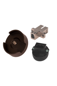
- Try a different instrument (interchangeable) connector adapter. There have been occasions where these get broken / bent / worn out, and a different adapter will show the problem. This also typically shows as an unstable reading.
An optical power reading seems low at high power levels:
If measuring transmission equipment power levels, it is possible for signal modulation to cause a false reading. This problem is worse at high power levels, and diminishes rapidly as the power level drops. To observe (and cure) this, attenuate the signal into the meter (about 10 dB is good for a trial), and see if the reading comes to the expected value.
A laser source doesn't seem very stable:
- Laser sources achieve their best stability when used in a low reflection environment, which includes the connector going into the meter. To obtain optimum stability, use good PC or APC connectors, and use an APC connector into the power meter at the other end. Ensure all connectors are clean and tight.
- The source may need warming up for about 15 minutes. This applies each time the laser is turned on or off, or if the wavelength is changed. This applies to all brands of sources.
- The source stability specification may be qualified by an extensive warm up period, may be only valid at a stable temperature, and stability specifications are interpreted as follows: A +0.1 dB meter reading followed by a -0.1 dB meter reading is a specification of 0.1 dB. For example, if the meter reading varies from -6.00 dBm to -6.20 dBm. this is also a stability of 0.1 dB.
- Try a different instrument (interchangeable) connector adaptor. There have been occasions where these get broken / bent / worn out, and a different adaptor will behave differently.
An attenuation value seems wrong:
Refer to the meter manual to find out how to take a reference value correctly. Refer to our Application Notes if you are not sure how to use reference values during attenuation measurements.
The instrument is suspected of malfunctioning:
Instrument manuals can be downloaded from this web site. In the back of most instrument user manuals, there is a detailed Performance Verification Test which can usually be performed with quite simple equipment. If this test fails, please contact a service center. Any test results you have available will help identify the problem.
The optical connector fails to latch onto the instrument
Applies to instruments with an SC style interchangeable connector: Usually, this is because you are trying to use a heavily-worn through-connector. Use a brand new though connector (might need to try a couple of different brands of through connector) to fix this problem.
Instrument (KI6680, AutoGet Wi-Fi) won't connect to an Android or iOS devices via Wi-Fi
- Make sure that Wi-Fi on instrument is turned on (indicated by a stable green LED light on KI6680)
- Make sure that your android/iOS device (which the instrument is to be connected with) Wi-Fi is turned on
- Make sure that the password, “12345678” is entered when prompted on your device
- To verify if the Wi-Fi function on instrument is faulty:
- Verify that the Wi-Fi function of a Windows 10 computer is working (e.g., try connect it with another device)
- Check that if instrument is able to connect to that computer. The SSID of instrument (e.g. EasyGet_xxxx or AGWxxxx) should be visible on the computer.
- If the outcome of ii. above is “yes”, the instrument’s Wi-Fi function is good.
- If the outcome of ii. above is “no”, very likely that the instrument’s Wi-Fi function is faulty.
I need help running KITS™ Software:
Please visit the KITS™ FAQs for common problems, or take a look at the help file for your version of KITS™ software by clicking the help menu item.
KITS software has a detailed 85 page user manual, please have a look if this can help you.
I have another problem:
Please check our support page for next steps.


