Introduction
Optical Return Loss (ORL) or Back Reflection may affect fiber optic systems with one or more characteristics:
- Laser transmitters.
- Analogue transmission.
- Link has optical connectors.
What is back reflection or return loss?
It is the % of power reflected back in relation to forward power at a particular point in a light path.
Optical Return Loss Meters and Back-reflection Meters make the same measurements.
Is there a difference between Optical Return Loss and Back-reflection?
Scientifically, optical return loss (ORL) is the inverse of reflectance, and has the opposite sign, e.g. -50dB reflectance is 50dB return loss. However, there is a widely conflicting common usage of these and related terms, so unfortunately there is no safe assumption about which is what, so it's best to look for context.
Our definition of return loss is the accumulated % of power reflected back in relation to total forward power at one point, typically at an ORL test instrument!
This is usually not exactly the sum of all the individual reflections, due to attenuation in both directions along the light path.
For example, if a point somewhere along a fiber link has a reflection of -20 dB, and the fiber attenuation to that point is 10 dB, then the measured return loss contribution due to that point will be -40 dB. (e.g. the back reflection + 2 x the attenuation)
Back reflection from a particular point and measured return loss may be similar if there is negligible loss between the loss point and ORL meter, and if this loss point is the dominant source of reflected light.
Relationship between ORL and system performance
Reflection related system issues can be quite baffling, since loss & power levels check out OK, but data transmission shows excessive errors or degradation.
Sensitivity to reflection often varies widely from transmission unit to unit, which is frustrating. So, in a line with poor or average ORL performance, just swapping equipment around may fix the problem. This is a genuine practical fix, however it may need recording and tagging.
This also gives a clue: the relationship between ORL and system performance can be vague. It may be good to follow up with an optical margin & BER test.
Measurement units
By convention, test instruments usually display a negative dB ORL number. 0 dB return loss implies a perfectly reflective system. A large negative number implies little reflected power.
Theory
The Fresnel formula for a simplified reflection where the incident angle is normal, is (dB units) R =10 x log(((n1-n2)/(n1+n2))2)
the refractive index of air = n1 = approximately 1.00029 at standard temperature & pressure.
the refractive index of glass core = n2 = approximately 1.476 in most fibers
Causes
- Intrinsic material scattering (called Rayleigh scattering) in glass produces small levels of back reflections. Because of backscatter, a link will produce intrinsic reflections which are dependent on the length (ignoring end reflections), shown in the table below.
- A sudden change in the refractive index of material through which light is travelling. This is most commonly a glass / air interface, which produces about -14.3 dB back reflection from e.g. an unmated PC connector end in good condition.
- Some wavelength selective devices reflect rejected wavelengths. This can cause major problems.
The most common glass/air interface is a connector end or inside an opto-electric device. In the case of a mated flat-polish connector with a small air gap, there are two glass / air interfaces, resulting in roughly twice the reflection, e.g. approximately 11 dB. We have seen systems with high connector density, where the return loss was about 6 dB, which was sufficient to disrupt transmission from a simple 1 MHz analogue signal produced by a LED.
The effect of joining fibers depends on the splicing method. Fusion splicing tends to produce negligible reflections. However mechanical splices can result in high reflection levels, depending on the exact splicing and method used. This is one of many reasons why a fusion splicer is the preferred method of jointing.
Intrinsic fiber back reflection
Intrinsic fiber back-reflection due to Rayleigh scattering is approximately:
| Link length |
Return loss due to Rayleigh Backscatter |
| 1 meter |
70 dB |
| 10 meters |
60 dB |
| 100 meters |
50 dB |
| 1Km |
40 dB |
| Infinite |
32 dB |
This limits the sensitivity of a typical return loss test set-up, which is dependent on the length of attached fiber.
For example, to use a return loss meter to -70 dB sensitivity would require a total fiber length of less than 1 meter, or 10 meters if the instrument has a "zero offset" function.
Another problem with very sensitive measurements, is that low levels of stray ambient light can leak in and create a false reading.
Effect of fiber types
Single mode fiber applications are traditionally associated with ORL sensitivity problems, since they have always used lasers, are typically higher data rates, and may have longer links with little performance margin.
In contrast, old multimode applications used LED sources (which are insensitive to ORL issues), lower data rates and typically relatively short links. However in recent years, multimode systems have transitioned to VCSEL lasers, high data rates, and may be operating much closer to their length limit, so ORL has become an issue. Typically, to reduce the sensitivity of these lasers to reflections, the output laser-to-fiber coupling ratio is kept very inefficient. However, there are still an increasing number of occasions were ORL contributes to a performance problem.
Technically, the overall causes of reflections in both types of fiber are similar, however connector ORL performance is different.
Optical connector ORL performance
Single mode Physical Contact PC polish (blue colour) connectors have very variable Optical Return Loss performance. It is largely for this reason that Angled Physical Contact APC polish (green colour) connectors have become preferred in many situations.
PC connector performance varies dramatically between mated and un-mated states and is also critically dependent on tiny amounts of dirt, which can stop the two fiber ends from contacting each other, although the optical loss may still be still quite small. Various qualities of PC polish connector can achieve between typically -50 dB to -30 dB when mated nicely, -14.3 dB when un-mated, and as poor as -11.3 dB when poorly mated.
The performance of APC connectors is overall much better, with an un-mated or mated return loss of better than -60 dB. the return loss does improve when mated properly.
Multi-mode connectors (beige) are usually PC polish, and do not have very good ORL performance in comparison to single mode connectors. Use of APC connectors on multimode systems is rare. The problem with these connectors is that the physical contact zone may not cover the entire connector core, so good mated ORL performance may be around -20 dB. Un-mated or poorly mated performance is similar to SMF, e.g. -14.3 or -11.3 dB.
Note that there are many styles of connector. The above figures apply to commonly available types with a ceramic ferrule. ORL performance may also be lower depending on the exact polishing procedure.
System performance effects
- Increased receiver noise due to reflections bouncing around the transmission lines and then entering the receiver.
- Increased transmitter power & wavelength noise due to reflections causing unwanted resonances in the laser.
- In a typical digital system, it will result in the eye diagram closing a bit or can be expressed as a dB transmission impairment.
- The effects can be very polarization sensitive. So, to perform proper characterization, some sort of polarization controller may be needed. This is particularly the case with laser instability problems.
- DFB lasers are particularly susceptible to reflections and may require an ORL level as low as -50 dB to operate to specification. Since the intrinsic link backscatter is generally higher than this, an isolator is positioned near the laser, or is built into the laser package, to reduce the reflection level seen by the laser.
- In many cases where reflection is an issue, the limits for the installed system and the transmitters may be different. The cable system specification may be in the region of -30 dB, to prevent excessive receiver noise caused by the signal bouncing around the link. The transmitter specification may be in the region of -50 dB, to prevent spurious operation of the laser.
- Reflections caused by material scattering may have a different effect to reflections caused by a point event. A point reflection will cause a sudden impulse of reflected light, whereas backscattered light is a very low-level distributed reflection. Therefore, in some critical applications, connector reflections of -60 dB might be specified in a link with -32 dB inherent backscatter, to reduce the effect of sudden impulse reflections.
How to test ORL
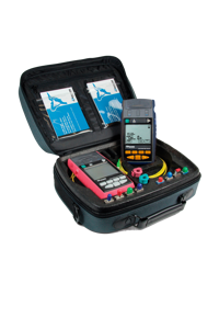
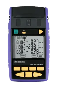
It is convenient to measure return loss with an optical return loss meter (or ORL meter or back-reflection meter or optical continuous wave reflectometer or OCWR).
Back reflections of individual components can sometimes be measured with an OTDR; however this is generally of limited accuracy, and in some situations the back reflections may cause saturation of the instrument input amplifier, making measurement impossible. So, return loss meters are commonly used for acceptance work.
Some ORL meters can use automation to work as a pair, and measure return loss each end of a system while simultaneously performing a two-way attenuation measurement, which achieves a total analysis with no extra effort.
Better ORL meters have a couple of standard features which are both very helpful:
- The ability to "zero" a residual ORL level improves linear measurement range by about 14 dB. For example, if a measurement set up has a residual level of 50 dB, if this 50 dB residual level is "zeroed", the meter can then read accurately to about -60 dB. Linearity around 46 - 50 dB is also improved.
- The ability to apply an offset to the measurement. For example, a measurement set up has a loss of 0.5 dB due to connections etc. This will cause readings to be offset by 1 dB, so a 1 dB offset can be applied by the user to correct this.
Connector return loss measurement challenges commonly depend on the connector end polish. A PC polish connector with a performance of around -40 dB is a lot easier to measure than an APC connector, which is normally un-measurably low.
A tight mandrel (a rod of around 5 mm diameter) can be a very useful ORL testing accessory, used to create a temporary extra loss / isolation to determine where a reflection is coming from.
Solutions to back reflections
To reduce back reflections:
- Remove their source by using low reflection connectors (preferably APC polish) and low reflection (fusion) splices.
- Do not forget the receiver, which may need a low reflection detector arrangement.
- Control reflections by installing isolators.
- There are now inexpensive transmitters available with built-in isolators, thus making the rest of the system less critical and easier to install and maintain.
- If system margin permits, then adding some attenuation just after an emitter, can be an effective way to reduce the impact of reflections on emitter stability.
Practical return loss testing and problems
Anyone using an ORL meter will probably need to be able to fault-find ORL issues.
- Return loss measurements tend to have a low level of confidence associated with them, so the measurement process must be as simple & reliable as possible, so that at least the displayed number can be relied on.
- You should know if you are evaluating a link for a general level of return loss in the -20 to -30 dB region, or the short link between an isolator and a laser, to a general level of -50 dB. The effect on a system of each item is rather different.
- You will need to understand reflection effects caused by connectors, splices etc, and also the intrinsic reflection levels due to Rayleigh scattering.
- You will need to know how to isolate sections of a link (e.g. by bending loss using a mandrel, or other), and create a low reflection termination (index matching gel, angled cleave, crushed end, damp finger). This is needed to help do the measurements and work out which section has a problem.


